Electrical Part
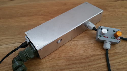
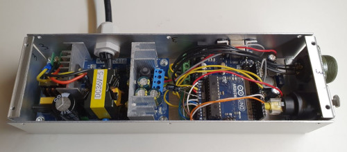
Electrical Box
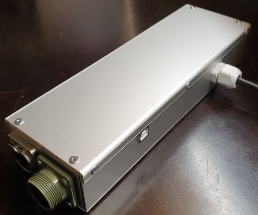
Note
There is another Electrical Box which is about 130$ cheaper but 15-20% slower and 40% less powerful (instead of 29 lbs thrust 17 lbs) The Box is 3D printed.
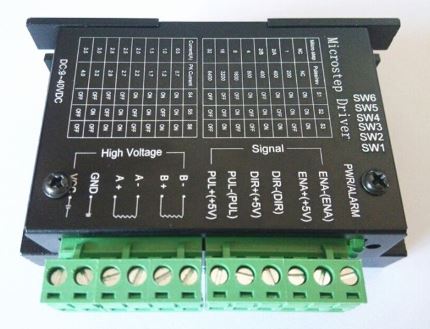
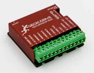
Driver : Cheap Driver Aliexpress
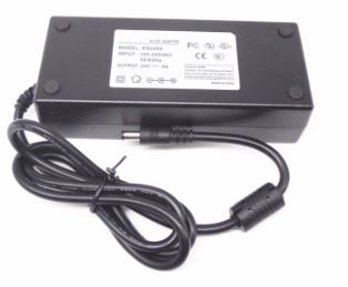
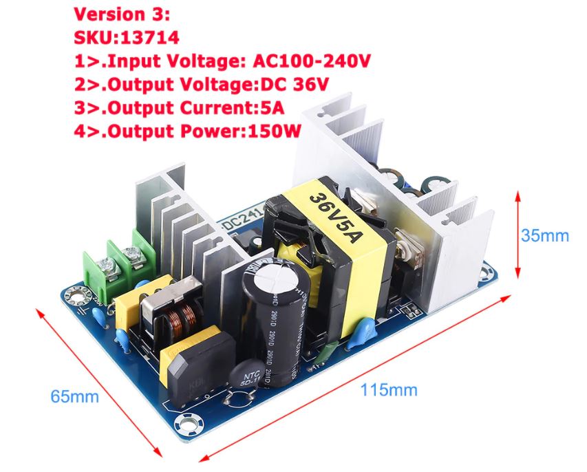
Power 24V, 6A : Power 24V 6A Aliexpress
Listing Parts

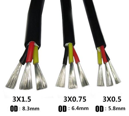
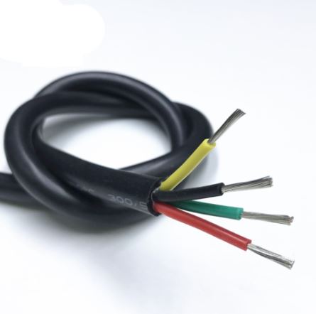
Cable Silicone 3 Cores
Length : 1x 2m
Type : 0.75mm^2
Note : I used silicone because it’s easy to fold.
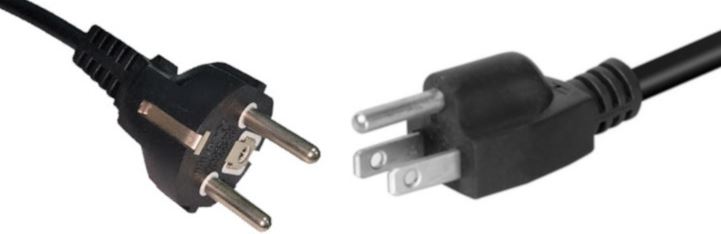
Plug 110 / 220 V
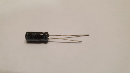
Capacitor Polarized 1uF
Quantity : 1x
Purpose : This reduce the noise while reading the speed on the remote-control
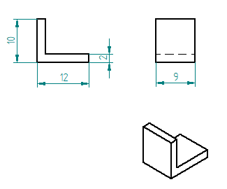
Square 10-12-9mm
Quantity : 2x
Material : aluminium
Purpose : Reinforcement of the fixaton (glue) of the Arduino Uno to the U Base
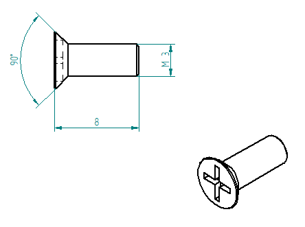
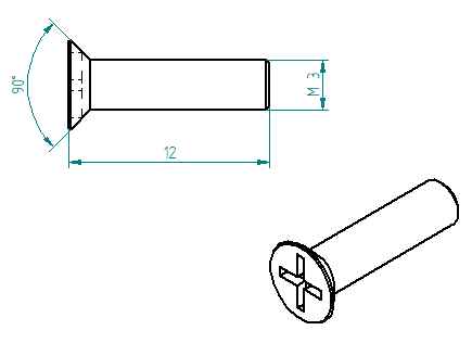
Countersunk Head Screw M3 x 8mm
Quantity : 4x
Material : Stainless Steel
Purpose : To fix Geckodrive on the U Base
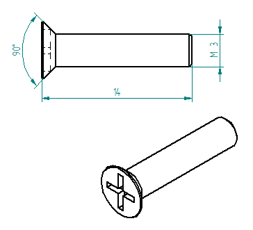
Countersunk Head Screw M3 x 12mm
Quantity : 4x
Material : Stainless Steel
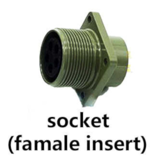
Purpose : To fix the Connector Socket 5 pins Female Insert on the U Right
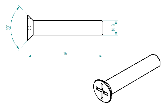
Countersunk Head Screw M3 x 14mm
Quantity : 3x
Material : Stainless Steel
Purpose : To fix the Power 36V on the U Base
Countersunk Head Screw M3 x 16mm
Quantity : 1x
Material : Stainless Steel
Purpose : To fix the Power 36V also the Ground Terminal on the U Base
Glue Silicone
Quantity : 1x
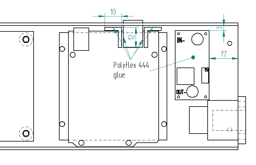
Type : Polyflex 444
Purpose : To glue the Arduino Uno to the U Base using the Square 10-12-9mm to fix stronger


Operation Plan
Make The Sheets Parts
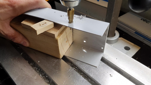
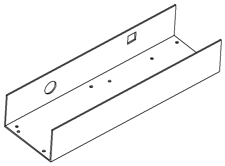
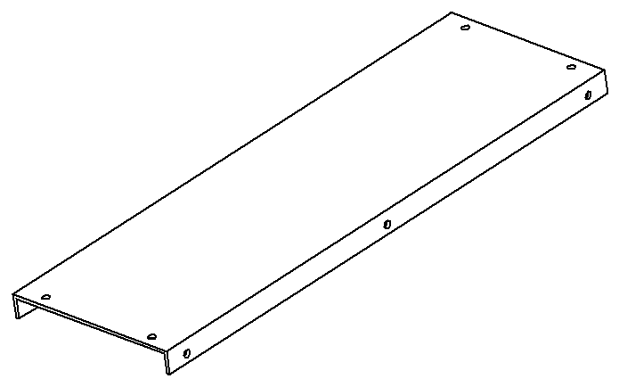
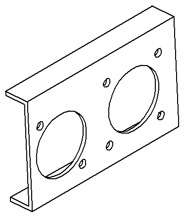
Make the U Base, U Right and the U Left following this Video, see also the drawings below :
Drawings :
Material : aluminium
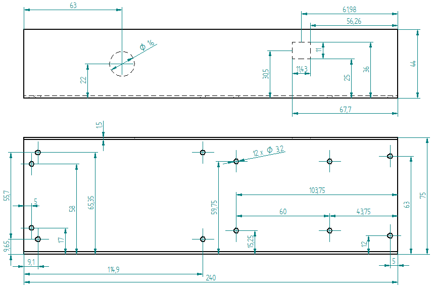
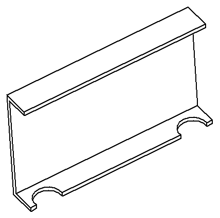
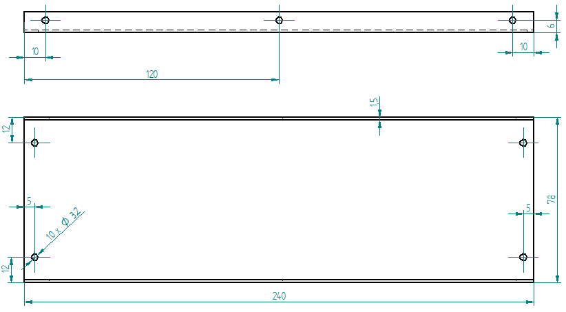
U Base
U Top
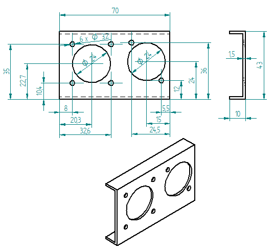
U Right
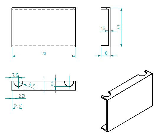
U Left
Make the Spacer 6-8-3mm
See the following video :
Drawing :
Quantity : 4x
Material : aluminium
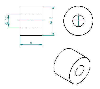
Spacer 6-8-3mm
Make the Square 10-12-9mm
See the following video :
Drawing :
Quantity : 2x
Material : aluminium
Square 10-12-9mm
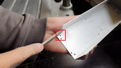
Scrape the surface on the U Base
File the bottom of the U Base (only the part where the red framed hole is) so that the grounding contact faces well. This operation is not necessary if you are using non anodized sheets.
Note
The anodized surfaces are not conductive.
See Video :
Control Power 36V
Control the voltage of the output of the Power 36V with a voltmeter. It should be 36V.
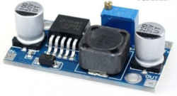
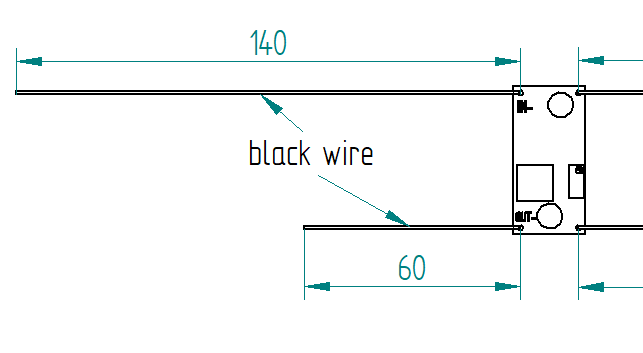
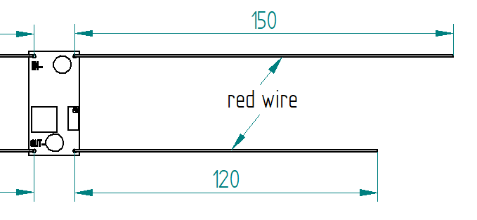
Adjust voltage Power 36/12V
Materials:
1 wire 0.5mm^2 red length = 120mm
1 wire 0.5mm^2 red length = 150mm
1 wire 0.5mm^2 black length = 140mm
1 wire 0.5mm^2 black length = 60mm
Sold the wire
Wire the Power 36/12V
Connect the Power 36/12V IN to the Power 36V OUT
Connect the voltmeter to Power 36/12V OUT
Adjust the voltage
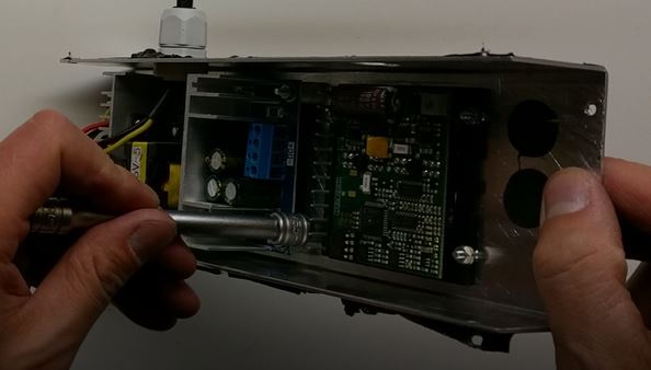
With a Screwdriver 0, adjust the voltage to 12V
Fix the Power Cable to the Electrical Box
See Video :
Strip the Cable Silicone 3 Cores at 10cm
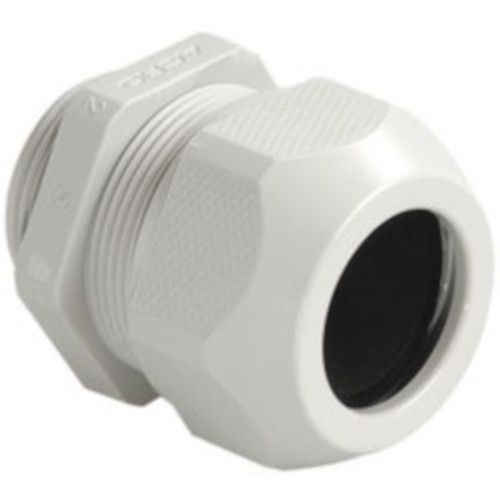
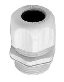
Fix the Cable Gland to the U Base
Tighten Cable Gland
Tighten the Cable Ties and cut it with a Cutting Pliers
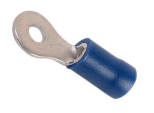
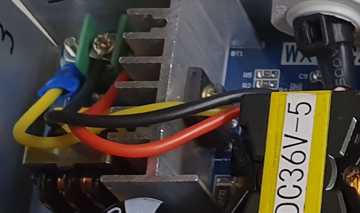
Tighten the Ground Terminal M3 on the ground wire (yellow)
Tighten the Phase and Neutre to Power 36V “IN”
Set Geckodrive current limit
For G203V :
Connect a resistor of 120kOhms between pin 11 and 12 of the GECKODRIVE. This will limit MOTOR current by 5A.
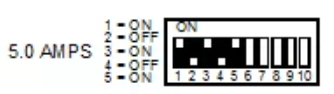
For G201X :
set the switches like the following figure
Screw the Power 36V and Geckodrive on the U Base
Note
Use Threadlocker Glue.
For Power 36V :
- Fix three corners of the Power 36V by using :
3x Spacer 6-8-3mm
3x Countersunk Head Screw M3 x 14mm
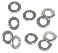
3x Washer M3
3x Nuts M3
- Fix the last cornerThe ground to the U Base by using :
1x Countersunk Head Screw M3 x 16mm
1x Washer M3
1x Nuts M3
1x Ground Terminal M3 (the ground on the Cable Silicone 3 Cores
Power 36V
U Base
GROUND
screw with Spacer
For Geckodrive use :
4x Head Screw M3 x 8mm
4x Washer M3
4x Nuts M3
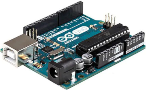
Glue the Power 36/12V and Arduino Uno
Glue the Arduino Uno at the U Base with Glue Silicone and Square 10-12-9mm and the Power 36/12V.
Wiring
See video :
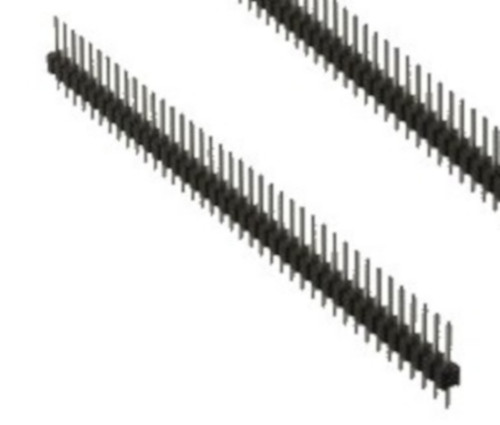
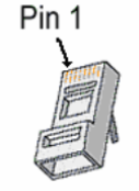
Sold the wires to the Male PCB PIN Header (15, 10, 8 pins), except the POWER 36/12V OUT+
Use two clamps this help to sold the Male PCB PIN Header
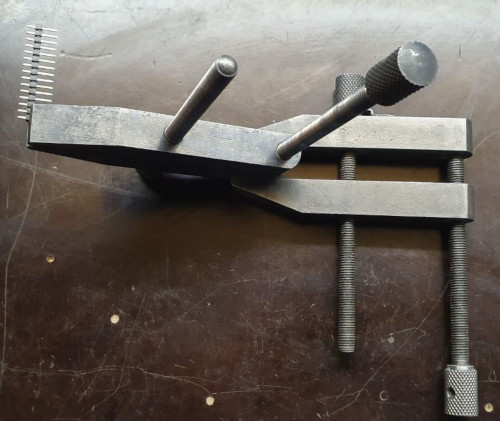
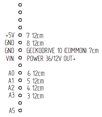
Male PCB PIN Header 15 pins
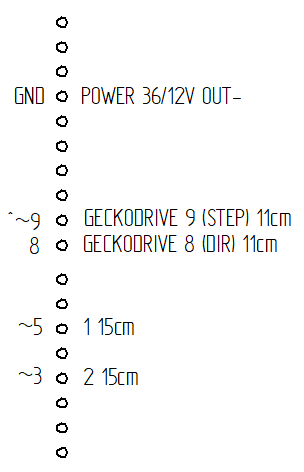
Male PCB PIN Header 10 and 8 pins
GECKODRIVE |
ARDUINO |
Cable Length |
|---|---|---|
8 (DIR) |
PIN 8 |
11cm |
9 (STEP) |
PIN 9 |
11cm |
10 (COMMON) |
GND |
7cm |
POWER 36/12V |
ARDUINO |
Cable Length |
|---|---|---|
OUT- |
GND |
6cm |
OUT+ |
VIN |
12cm |
ARDUINO |
RJ45 cable (inside Box) |
Cable Length |
|---|---|---|
A0 |
6 sold capacitor + |
12cm |
A1 |
5 |
“ |
A2 |
4 |
“ |
A3 |
3 |
“ |
~3 |
2 |
15cm |
~5 |
1 |
“ |
GND |
8 sold capacitor - |
12cm |
+5V |
7 |
“ |
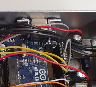
Sold the Capacitor between A0 and GND (8) see folowing picture
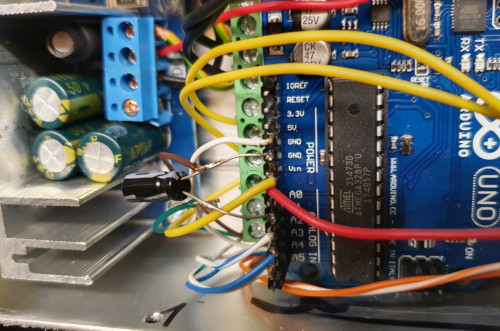
Connect :
Power 36V |
GECKODRIVE |
Cable Length |
|---|---|---|
-DC |
1 (POWER GND) |
6cm |
D+ |
2 (18 TO 80 VDC) |
“ |
Power 36V |
POWER 36/12V |
Cable Length |
|---|---|---|
-DC |
IN- |
14cm |
DC+ |
IN+ |
15cm |
GECKODRIVE |
Female Connector (MOTOR) |
Cable Length |
|---|---|---|
3 (WINDING A) |
A |
15cm |
4 (WINDING not A) |
B |
“ |
5 (WINDING B) |
C |
“ |
6 (WINDING not B) |
D |
“ |
Upload the programm to Arduino Uno and final control
Plug the PC using an USB cable to the Electrical-Box
Upload the programm (soon available)
Control if every thing is ok (the *Machine, Remote Control, Stepper Motor and the Rod should be done). Do all these steps showed in that video for the test :
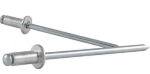
Cover with U Top and Rivet
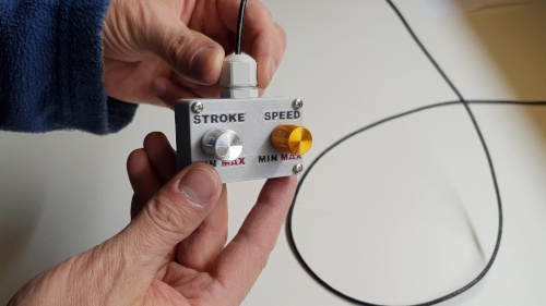
Remote Control
Listing Parts


Operation Plan
See the video :
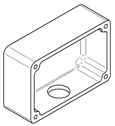
Make the Box
Print it in PLA. Infill = 50% File : soon available…
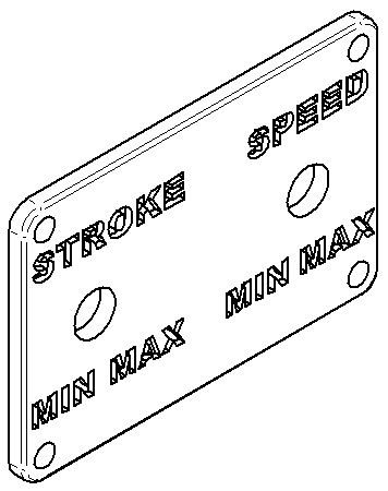
Make the Cover
Print it in PLA. Infill = 50% File : soon available…
Prepare the Epoxy with black pigment, red pigment and green pigment
Fill with pigmented Epoxy the inscriptions on the Cover
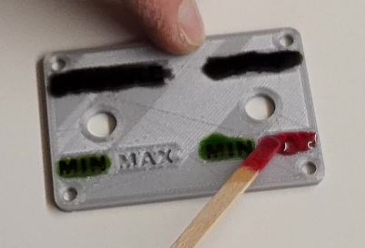
Cure the Epoxy then sand it very thin (60, 240, 400)
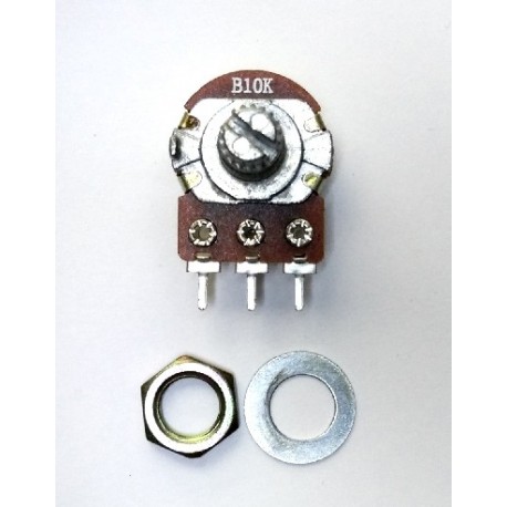
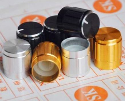
Place the Potentiometer (2x) and and tighten them
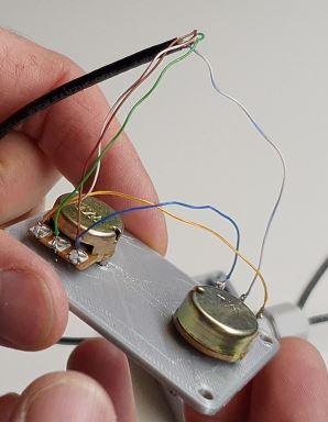
Wiring the Remote Control
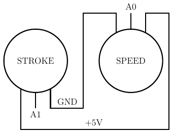
Remote-Control |
RJ45 cable |
Wire Color |
|---|---|---|
A0 |
6 |
G |
A1 |
5 |
b |
GND |
8 |
BR |
+5V |
7 |
br |
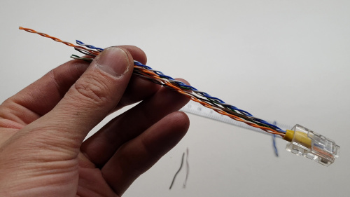
Strip the RJ45 Cable at 7cm
Cut the unused wire
Use the cutted unused wire to make the bridge between GRD and +5V inside the Remote Control
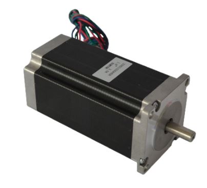
Motor
This section shows how to fix the Cable Silicone 4 Cores to the Connector Plug 5 pins Male Insert and the Motor
Listing Parts

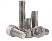
Screw Hex Head Allen M5 x 40
If the Motor isn’t fixed yet on the Machine, then 1x Screw is needed.
Quantity : 1x
Size : M5 x 40
Type : Stainless Allen Bolt Socket Cap Screw Hex Head Allen Key DIN912
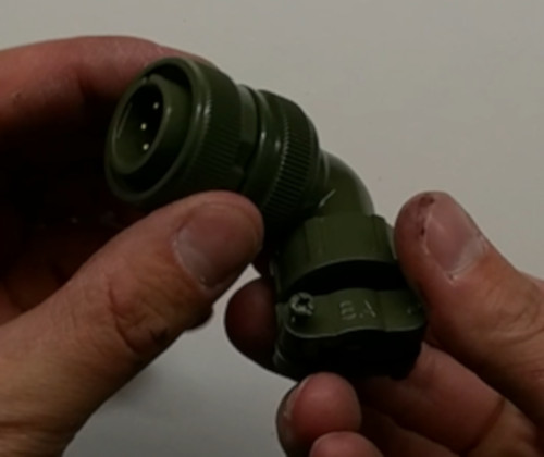
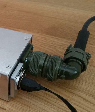
Connect the Connector Plug 5 pins Male Insert
Operation Plan
See the video :
Wiring
strip the cable at 3cm
strip the 4 wires and solder the wires
5cm from the edge roll up the 10-layers adhesive tape
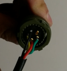
pass the cable and solder the wires in the plug in counter-clockwise order
black (A)
yellow (B)
red (C)
green (D)
assemble the plug and tighten the flange
Connect and fix the Cable Silicone 4 Cores to the Motor
Operation Plan
See the video :
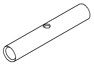
Make the Tube Cable Holder
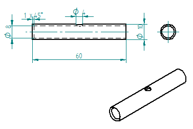
Tube Cable Holder (material aluminium anodized)
Unpacking and motor control. Plug the 4 wires on an Electrical Box and make it turn. This is important before making the following steps.
There are two kinds of motor a 3A and a 4.2A each motor has their own colors of wire. Depend on the Amps of the motor you use, cut the wire as follow :
Motor 3A :
red wire 47mm
yellow 57mm
blue 67mm
green 77mm
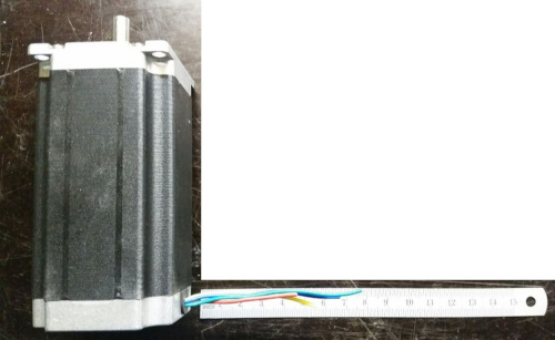
3A motor with wires cutted
Motor 4.2A :
red 47mm
green 57mm
black 67mm
blue 77mm
Stripping, twisting, tinning the motor wires to 5mm
Cut the Heat Shrink Tube to 37mm length and tighten it with industrial foehn. The red wire should protrude about 5mm..
Cut the Cable Silicone 4 Cores at 2.2m
Strip the Cable Silicone 4 Cores to 45mm.
Cut the wires on the Cable Silicone 4 Cores as follow: - red 40mm - yellow 30mm - black 20mm - green 10mm
Strip, twist, tin-plate the cable wires to 5mm.
Cut 4x Heat Shrink Tube at 13mm
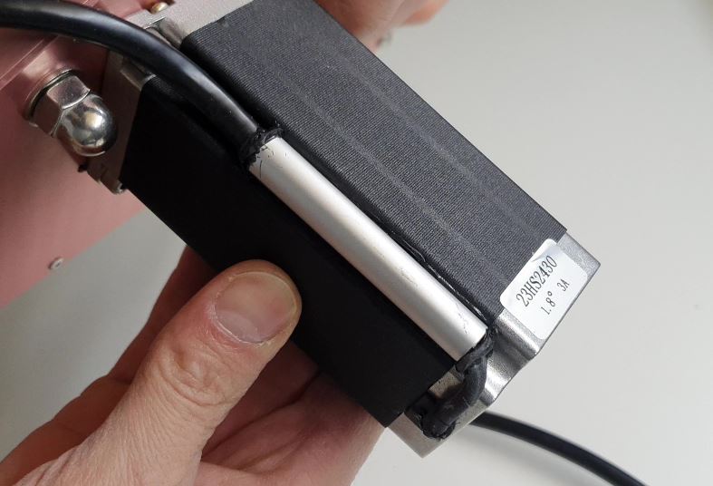
Put 13mm Heat Shrink Tube + Tube Cable Holder (pay attention to direction the chamfer 1x45) and solden
Degrease Tube Cable Holder, Cable Silicone 4 Cores and Motor with acetone
Warning
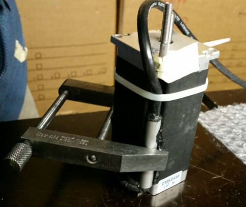
If the Motor isn’t fixed on the machine yet, then don’t forget to put the screw in the motor hole (see picture below)
Inject the Glue Silicone through the 4mm hole diam. until it comes out of both sides of the Tube Cable Holder; take the surplus and apply it to the Motor on the groove where the Screw Hex Head Allen M5 x 40 has been placed; turn the Tube Cable Holder so that the injection hole is against the Motor and is not visible; put a Cable Ties on the Cable Silicone 4 Cores , put the Tube Cable Holder on with the clamp see following picture
if necessary, inject at the end of the Tube Cable Holder where the chamfer is located and put some Glue Silicone on the Motor if you see the wires that protrude a little beyond the Heat Shrink Tube
Allow to harden; clean and remove the beads on Tube Cable Holder.